Ravenbrook / Projects / Perforce Defect Tracking Integration / Project Documents
Perforce Defect Tracking Integration Project
This document extends the architectures proposed in "Architecture Proposals for Defect Tracking Integration" [GDR 2000-05-08]. For each architecture I've determined:
The purpose of this document is to reveal how these aspects constrain the implementation of these architectures, so that the architecture analysis [GDR 2000-05-30] can be more accurate.
The readership of this document is anyone interested in the project.
This document is not confidential.
The blue boxes and text in the diagrams in this section show the potential divisions between hosts on a network.
The red text shows the potential divisions between operating systems. In each diagram I have selected as many different example operating systems as possible to show how many could be involved. These combinations aren't releastic -- in fact they're pretty perverse -- but they show how many systems might be used in some cases. See "Platform Survey for Perforce Defect Tracking Integration" [RB 2000-06-20] for realistic combinations.
Multiple instances of a process are indicated by stacked boxes and multiple arrows between boxes.
In the tracker client architecture the defect tracker and the Perforce client library must run on the same host. The interface between them is a C++ call interface, and the user will expect the workspace to be on the same machine as the defect tracker client. See figure 1. Note that this diagram doesn't show the multiple instances of the client.
The Perforce server can run on a remote host as usual.
Figure 1. The tracker-client architecture with platform annotations.![]()
We've assumed that there is just one replication daemon connecting one Perforce server to one defect tracking database. However, some Perforce clients run more than one Perforce server [RB 2000-06-20] and some run more than one defect tracking server, or even more than one defect tracking system! The replication architecture could be extended to cope with these scenarios, but the potential for inconsistency would increase.
Figure 2. The replication architecture with platform annotations.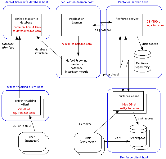
The most important thing to note about the union architecture is that the database unifier can't really run on a separate host to the Perforce database. This means that the unifier must be as portable as the Perforce server, and be ported to all Perforce server platforms. It also means that the defect tracking database interface has to go across the network to the unifier, which may introduce serious performance problems. Some defect trackers don't have such an interface.
Figure 3. The union architecture with platform annotations.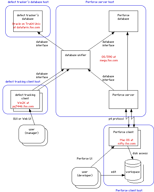
In the variation of the union architecture, the unifier may need to make multiple connections to the Perforce server so that the user names are correctly recorded. It may be that the same is true for the database server. In other ways this architecture is very decoupled from the platform and host configuration.
Figure 4. The variation of the union architecture with platform annotations.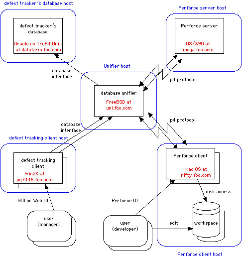
The main thing that the analysis of the single-database architecture reveals is that the interface between the Perforce server and the database interface module must be a network protocol. The set of platforms on which the interface module can run is limited (mostly just Windows NT) and the Perforce server can't be similarly constrained. This means there must actually be another part between the two produced by this project.
Figure 6. The single-database architecture with platform annotations.
Figure 7. The manual architecture with platform annotations.
This analysis has revealed some important difficulties with some of the architectures:
These will be incorporated into the architecture analysis [GDR 2000-05-30].
| [GDR 2000-05-08] | "Architecture Proposals for Defect Tracking Integration"; Gareth Rees; Ravenbrook Limited; 2000-05-08. |
| [GDR 2000-05-30] | "Analysis of architectures for defect tracking integration"; Gareth Rees; Ravenbrook Limited; 2000-05-30. |
| [RB 2000-06-20] | "Platform Survey for Perforce Defect Tracking Integration"; Richard Brooksby; Ravenbrook Limited; 2000-06-20 |
| 2000-06-08 | RB | Created based on paper diagrams and meeting notes from yesterday. |
| 2000-06-09 | RB | Fixed a couple of mistakes pointed out in mail from GDR. |
| 2000-06-21 | RB | Added text from original paper notes. Added conclusions section. |
| 2000-06-30 | GDR | Made references link directly to target, rather than the references section. |
Copyright © 2000 Ravenbrook Limited. This document is provided "as is", without any express or implied warranty. In no event will the authors be held liable for any damages arising from the use of this document. You may make and distribute verbatim copies of this document provided that you do not charge a fee for this document or for its distribution.
$Id: //info.ravenbrook.com/project/p4dti/doc/2000-06-08/platform-analysis/index.html#11 $
Ravenbrook / Projects / Perforce Defect Tracking Integration / Project Documents